
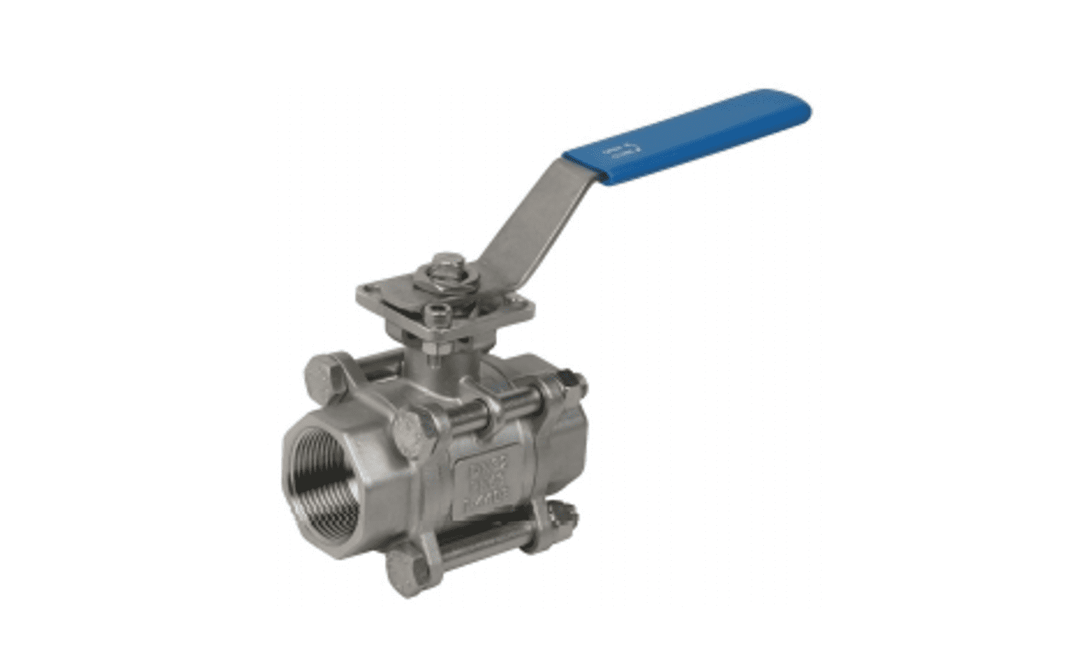
Series. M311 3 piece Ball Valve
1000 WOG
3 piece Ball Valve
1000 WOG
▪ High quality investment casting
▪ Full bore design
▪ Blow out proof stem
▪ ISO 5211 Mounting flange for actuator
▪ Min. wall thickness design according to EN 12516-1 (PN16)
▪ Test Pressure: API598/EN 12266-1
Hydrostatic test:
1.4408- 1500 PSI
Seat(air) test: 80 PSI (6 Bar) under water Seat(water) test: 1100 PSI
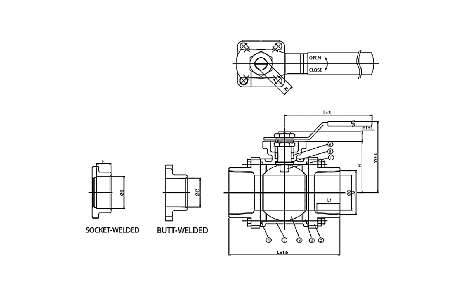
Orifice DN 8 to DN 100
Material
Body CF8 (DIN 1.4308), CF8M (DIN 1.4408), WCB (DIN 1.0619)
End Cap CF8 (DIN 1.4308), CF8M (DIN 1.4408), WCB (DIN 1.0619)
Stem material 304SS, 316SS
Ball 1.4308, 1.4408
Seal Material
Main Seal PTFE or RPTFE
Body Seal PTFE or RPTFE
Stem Seal PTFE/RPTFE with FKM O-ring
Option MG 1241 (Steam), TFM4215, TFM 1600, PEEK
Handle Material SUS304/Carbon steel
Media Gaseous and liquids that is compatible with the selected material
Media Temperature -10°C to +180°C (PTFE Seat)
-10°C to +200°C (MG 1241 Seat)
End Connections Standard: Threaded Ends, BW, SW
Options: Male thread, Tri-Clamp, Quick Coupling, Flange
Pressure Rating 0 to 63 bar (PN 63), 1/2” to 4”
Options Degreased, Anti static, V-port ball, Lever with locking device
Installation If required
Principal technical data
| Size | ØD | N | M | L | H | H1 | L1 | E | W | ØB | F | ISO 5211 | Weight(kg) |
| DN8 | 11.2 | 9 | G1/4“ | 50.0 | 32.4 | 7.6 | 10.0 | 120.0 | 71.0 | 17.52 | 11.1 | F03/F04 | 0.30 |
| DN10 | 12.7 | 9 | G3/8“ | 50.0 | 32.4 | 7.6 | 10.0 | 120.0 | 71.0 | 17.52 | 11.1 | F03/F04 | 0.39 |
| DN15 | 15.0 | 9 | G1/2“ | 66.0 | 35.0 | 8.0 | 14.0 | 120.0 | 79.0 | 21.71 | 12.7 | F03/F04 | 0.61 |
| DN20 | 20.0 | 11 | G3/4“ | 74.0 | 40.0 | 10.0 | 14.0 | 120.0 | 89.0 | 27.05 | 14.3 | F03/F04 | 0.61 |
| DN25 | 25.0 | 11 | G1“ | 84.5 | 43.4 | 10.0 | 19.0 | 152.0 | 95.0 | 33.78 | 15.9 | F04/F05 | 0.87 |
| DN32 | 31.8 | 11 | G1-1/4“ | 100.0 | 51.4 | 10.0 | 22.0 | 152.0 | 98.5 | 42.54 | 17.5 | F04/F05 | 1.46 |
| DN40 | 38.0 | 11 | G1-1/2“ | 110.0 | 56.0 | 10.0 | 22.0 | 190.0 | 118.0 | 48.64 | 19.1 | F05/F07 | 1.87 |
| DN50 | 50.0 | 14 | G2“ | 129.0 | 64.5 | 13.0 | 24.0 | 190.0 | 125.0 | 61.11 | 22.2 | F05/F07 | 3.00 |
| DN65 | 64.0 | 17 | G2-1/2“ | 168.7 | 91.0 | 16.0 | 24.0 | 350.0 | 158.0 | 73.81 | 29.5 | F07/F10 | 6.30 |
| DN80 | 76.0 | 17 | G3“ | 182.5 | 99.6 | 16.0 | 24.0 | 350.0 | 168.0 | 90.2 | 31.0 | F07/F10 | 9.70 |
| DN100 | 98.0 | 17 | G4“ | 221.5 | 120.0 | 16.0 | 24.0 | 350.0 | 188.0 | 115.06 | 39.0 | F07/F10 | 16.6 |